Possible causes for damaging an ECU
Spiked by careless welding, i.e MIG welding without disconnecting the battery
True
Enclosure seal damaged and with obvious sign of water ingress.
True
Faults are much more likely to be with connections or sensors.
True
Discuss how these ECU issues should be incorporated into diagnostic practices to test an ABS system.
While testing the ABS sytem, one should be careful about testing the component of ABS. ECU components are so closely welded up so it must be careful while testing between different components. During welding the components in ECU, the welding spikes of different components can touch each other and during operation or voltage supply it may short circcuit the components or can give worng signal or voltage output. Same is for water in vapours in ECU.
1 = Wheel 5 = master cylinder
2 = sensor 6 = caliper
3 = reluctor wheel 7 = booster
4 = modulator
Wiring Diagram Practice
Using the wiring diagram in the workshop manuals identify the wheel speed sensors and list their wire colours for each sensor.
Front right: A 10, Black and White
Front left: A 9, Green and Red
Rear left: A 22, Blue and pink
Rear right: A 23, yellow and brown
In the ABS wheel sensor what is the reason for the braded wire?
To cancel out the effect induced emf in two wires. When the current pass through two wire, running parallel to each other, the induced emf produces in both wires which interfere the signal to ECU.
Identify and list all the fuses that are used by the ABS circuit
Fuse box, Gauge fuse, Dome fuse, Stop fuse and ECU fuse.
Identify the earth for the ABS control unit and ABS motor their wire colours what pins numbers.
ABS control unit: 1 White and Black
ABS motor: 1 White and Black
On the wiring diagram for the ABS actuator, identify which solenoids control which wheel cylinder. Then note the wire colours and numbers
Front Right Wheel:
Pin number: 2,6
Wire colour: Red White, Red Green
Front Left Wheel:
Pin number: 3,7
Wire colour: Blue Red, Blue White
Rear Left Wheel:
Pin number: 1,5
Wire colour: Brown White, Brown Red
Rear Right Wheel:
Pin number: 4,8
Wire colour: Green Brown, Green Yellow
Q. In the four cases above, state when the ABS motor will be working
A. When there is increase and decrease in pressure in hydrolyic break lines.
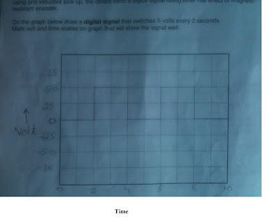
Conversion of frequency into time:
T=1/F
= 1/0.5=2s
ABS Demonstrators:
Left front ECU Pin # 2O and 2P
Left rear ECU Pin# 2R and 2Q
Right front ECU Pin# 2N and 2M
Right rear ECU Pin# 2S and 2T
Q. By looking at the wiring diagram, what type of speed sensor is this?
A. Inductive.
Q. Describe how it works.
A. Sensor consist of a winding and a magnet. The wire is winding over a permanent magnet. There is a toothed wheel rotating along vehicle wheel close to sensor. During the rotation of the wheel, the teeth of the sensor rotor pass close to the sensor pole piece. When the tooth of the sensor rotor comes near the sensor pole piece, it enhances the strength of the permanent magnet. This increases magnetic flux induces the current in the windings in one direction. When the sensor rotor teeth moves away from the sensor pole, the strength of the magnet diminishes. This causes the collapsing of the magnetic flux across the windings, which induces the current in the windings in opposite direction and hence this sensor generates the AC current in its windings.
Q. Locate an oscilloscope. Turn it on and set it up to be fully operational. What oscilloscope are you using?
A. Tektronix TDS 1002.
Wave form for left front wheel senor
Wave form for Right front wheel sensor
Wave form for left rear wheel sensor
Wave form for right rear wheel sensor
Q. Are all waveform exactly the same?
A. No.
Discuss what are the differences and what can cause these differences between the waveforms.
Both left and right front wheel sensors have lower amplitude than the rear wheel sensors but they have the same frequency. This means that there might be some wear and tear in the teeth of front wheel sensors which cause the low amplitude of voltage in their waveforms.
With the wheel sensors spinning, measure AC volts with a multi-meter and record here:
Left front 3.2V
Left rear 2.7V
Right front 4.1V
Right rear 2.9 V
Q. Can a multimeter be as accurate in finding problems with the wheel speed sensor as an oscilloscope?
A. No
Discuss what the oscilloscope could find that the multimeter can not find and why?
Oscilloscope can find the variation in AC voltage from its lowest value to the highest value in the sign wave but multimeter will show us the average voltage only. For example if the AC signal varies between 0 to +5 and -5, the voltmeter will display 2.5 volts on its screen.
Relay waveform
Explain with arrows what is happening in the waveform above.
A is the point where the voltage in the circuit was zero just before the closing of the switch to the relay. when the switch turned the relay on, the potential difference starts building up but as the windings are not grounded to earth on other side of the relay (85), the oscilloscope shows 12 V as shown at B in above graph. The switch side in the relay is still at 87a because the windings are not grounded and there is not the current flowing through the windings and hence there is no magnetic field around them to pull the switch down to 87 and the voltage on oscilloscope shows zero ( till F). Once the relay winding grounded by the transistor, the current starts flowing through the windings hence makes the oscilloscope to read zero voltage at 85 (C). The magnetic field starts building up around the windings. Because of the magnetic fields, the switch pulled down to 87 and now the oscilloscope reads 12 V at 30. When the windings disconnected from the ground, the oscilloscope reads 12 V at 85 as shown in above graph at D and at the same time the switch in the relay goes back to its original position at 87a, and the oscilloscope reads zero volts as shown in above graph at G. Again the windings are grounded by transistor and oscilloscope shows zero voltage, this time the windings remained grounded for a long time as shown in the above graph at E which pull the switch to 87 and hence the oscilloscope reads 12 V again at 30 as shown in above graph at H. there are some vibration in the relay switch as shown in above graph at I.
ABS Pump Relay waveform:
Explain with arrows what is happening in the wave form above.
The voltage at A in above graph is the voltage just before the relay turned on by the outside switch. When the switch turned on, the current will not flow through the windings as the 85 is not grounded yet by the transistor. The oscilloscope graph will read 12 volts (supply voltage) as shown in the above graph at B till C. Once the 85 is grounded to earth by the transistor, the oscilloscope graph went down to zero volt as shown at D in the above graph, the current starts flow through the windings and the magnetic field starts building up. The magnetic field quickly pulls up the relay switch to 87 which turns the pump motor on by giving the power supply to the motor as shown above in the graph at I. When the relay disconnected at 85 by the transistor, the switch turned the pump motor off as there is no current flowing through the windings and hence no magnetic field to keep the switch connected to 87. The oscilloscope read 12 V at 85 as shown above graph at F but as the pump motor was turning off, the graph voltage did not drop at once to zero as shown in above graph at J, K and L because there was back emf developing inside the motor winding which opposed the current to become zero.
Happening during ABS Self Test:
When we first turned the key on, the oscilloscope showed the above graph along with the warning light. As we have seen in the last graph (the graph above this graph), the pump relay switch stayed on even after the stoppage of current flowing through the coil. This is that time at which ABS does self test and the waring light stays on.
Create a fault in the system by slowing down a wheel speed sensor:
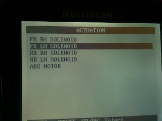
When we slow downed the right wheel manually while applying the break along with it, we heard the noise in ABS. In this process the ABS pump and outlet valve solenoid turned on while the inlet valve solenoid turned off. During this operation the hydraulic pressure gauge for this wheel went down, showing that the pressure in this circuit has decreased.
Catch an oscilloscope pattern when an ABS solenoid has actuated. What is the pin and name of the solenoid?
A. 2, B19
Q. How did you do it?
A. We connected the positive oscilloscope wire to the solenoid wire in the control module by using the circuit diagram and negative wire to the earth. Manually we slow downed the wheel related to this solenoid while applying the break at the same time. This operation gave us the following wave pattern on the oscilloscope.
Oscilloscope pattern.
Time division: 25ms
Voltage division: 5 V.


